Input Ratings:
- Voltage: 18-30 VAC 50/60 Hz transformer of 40 VA or more.
- Zone Panel: 7.5 VA max.
- All VA specifications at 24 VAC.
- 18- or 20-gauge solid (not stranded) wire.
- 5% to 90% RH non-condensing.
- Shipping: -20° to 150°F (-29° to 66°C)
- Operating: -40° to 165°F (-40° to 74°C)
- Complies with FCC Class B, part 15 requirements

Recommended Thermostats
Programmable
TH5220D | TH8320U, TH8321U,
TH6220D (2H/1C only) TH4210D (2H/1C only) YTH9421C
Recommended Dampers
Damper
dampers call the Honeywell Zoning Hotline at
sure regulat- ing damper
Maximum Dampers
| Ambient Temp. | Maximum Damper VA per Zone | | 100°F (38°C) | 28.8 | | 160°F (71°C) | 16.8 |
Accessories.
| Accessory | Description | | 40 VA transformer* | AT140A1042* | | 75 VA transformer | AT175A1008 | | Discharge Air |
Mounting
- Mount the HZ322 TrueZONE panel near the HVAC equipment; locate it on a wall, stud, roof truss, or cold-air return.
- NOTE: The HZ322 TrueZONE panel can be mounted in any orientation; level it for appearance only.
- Please refer to TrueZONE Panel Frequently Asked Questions form 50-9694 for operating details
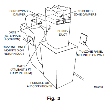
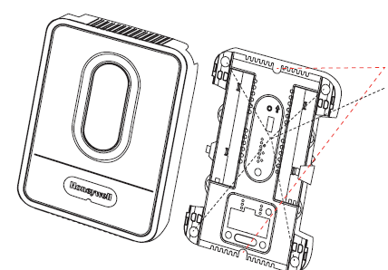
- Separate the zone panel cover from the base, and use the base as a template to drill mounting holes.
- Attach the base to the wall, stud, roof truss, or duct with appropriate screws (not included).
 Install thermostats using instructions provided with thermostats. Install thermostats using instructions provided with thermostats.- Connect thermostat to zone panel. To connect wire to the panel, strip approximately 1/4 in. of insulation and push wire into terminal. To release wire, press the button on top of the terminal.
- In retrofit applications, trim end of wire if not straight

- Install dampers using instructions provided with dampers. Connect dampers to zone panel.

Wiring
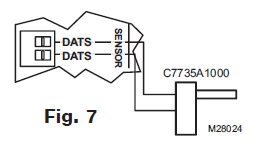
- Connect DATS as shown.
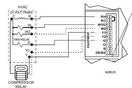
- Connect the equipment as shown.
- If using any wireless device, connect the ABCD terminals for the wireless interface module

- Connect the transformer as shown.


The following diagram is an overall view of wiring for a conventional system as depicted in steps 3–8.
Heat Pump

- Fig. 12. Zone panel wiring—heat pump with electric auxiliary heat.
- Use the following diagram for wiring a heat pump with electric auxiliary heat.
- NOTE: You can use a conventional thermostat for a heat pump system; however, em heat can only be controlled by heat pump thermostats. The diagram below shows a heat pump thermostat used with a heat pump system
To enter Configuration
- Press the Mode button (the Config LED will light up).

- Use the Back and Next buttons to navigate through the configuration menus. Pressing Next enters the selected option for that menu item and advances to the next menu. Adjust settings up or down by pressing the Adjust Setting button.
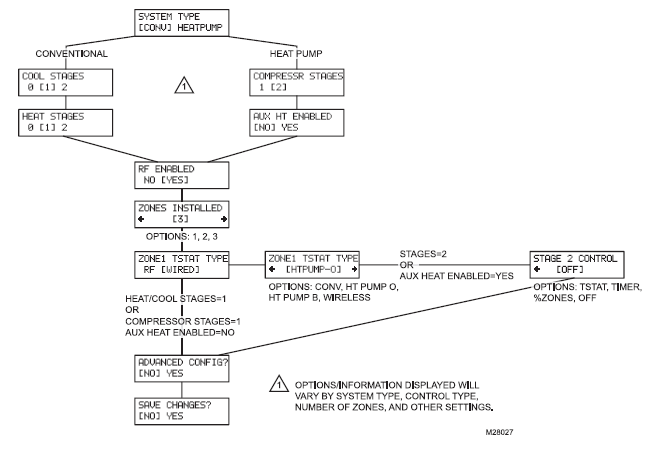
- The flow chart below illustrates basic zone panel configuration. For additional configuration, see Advanced Configuration on page 8. The label on the inside cover of the HZ322 Zone Panel also contains configuration information
CONNECT WIRELESS DEVICES
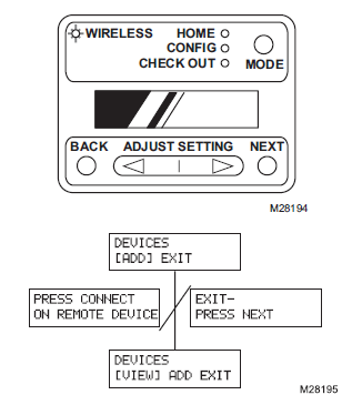
- Press the Mode button until the Wireless LED lights up. The TrueZONE must be configured for wireless devices to select Wireless mode
- Press Next to add devices.
- While the display alternates the Press Connect and Exit screens, push the Connect button(s) on the wireless device(s).
- Follow the instructions that came with the wireless device(s).
- Press Next to exit.
ADVANCED CONFIGURATION
top line)
Menu Options (LCD bottom
line; defaults in bold)
| [HVAC] PANEL | Fan control by HVAC | In heat mode, fan controlled by HVAC or turned
on by panel in call for heat.
[5 MIN] >

| 


 Install thermostats using instructions provided with thermostats.


